

It may not sound very much, less than three ounces, but in space a little thrust goes a long way. Boeing’s advanced XIPS thruster, which fires out Xenon ions at high speed, generates less than a quarter as much thrust from twice as much power. It’s used to maintain satellites in position, or move them to a slightly different orbit. Crucially, Xips weights about twenty kilos, more than an equivalent EmDrive, and the propellant for prolonged operation can weigh much more.
Nextbigfuture covered the EMDrive work back in 2008 and 2009 The heart of the Emdrive is a resonant, tapered cavity filled with microwaves. According to Shawyer, a relativistic effect generates a net thrust, an effect confirmed by various Emdrives he has built as demonstrations. Critics say that any thrust from the drive must come from another source. Shawyer is adamant that the measured thrust is not caused by other factors.
In 2008, professor Yang Juan of the College of Astronautics at Northwestern Polytechnical University (NPU) in Xi’an was happy to confirm that they were building an Emdrive.
Shawyer now estimates that the prototype superconducting thruster could be ready in 2016. He previously was talking about having such a system in about 2010.
Other coverage of the EMDrive at Nextbigfuture.
Superconducting EMDrive has not yet been built
The EMdrive enables superconducting cavities to very efficiently create static thrust. Thrust is measured in “pounds of thrust” in the U.S. and in Newtons under the metric system (4.45 Newtons of thrust equals 1 pound of thrust). 300 pounds of thrust is 1335 Newtons of thrust. 6 kilowatts of input means that 222.5 N/kW.
Apparently the 6.8 million Q device has 143 kg opf thrust from 6 kW input.
Effect of increased Q for the Emdrive
Q=50,000 (1st gen.) Static thrust=315 mN/kW Specific thrust at 3km/s=200mN/kW
Q=6,800,000 (supercond) Static thrust=222 N/kW Specific thrust at ??km/s=??N/kW
Q=5* 10**9 (supercond) Static thrust=31.5 kN/kW Specific thrust at 0.1km/s=8.8N/kW
Q=10**11 (supercond) Static thrust=630 kN/kW Specific thrust at 0.1km/s=??N/kW
Net thrust measurement of propellantless microwave thrusters (12 pages)
ABSTRACT – According to classical electromagnetic theory, this paper introduces a new kind of propellantless microwave thruster device for use in space propulsion. This device is able to directly convert microwave radiation into thrust without the need for any propulsion medium. The difference with traditional space propulsion devices is that this system means there is no need to carry a large propellant tank, and the problems of plume emissions polluting the space craft can be eliminated. The system comprises a frustum microwave resonator, microwave source, and load. The microwave source produces microwave radiation which can be input into the frustum microwave resonator and form a pure standing wave and electromagnetic pressure gradient. Thus, along the axial direction of the frustum microwave resonator, net thrust is formed. This article, based on the indifferent equilibrium principle, overcomes the weight and rigidity resistance of the thruster itself, and successfully measures the net thrust produced by the propellantless microwave thruster. The results show that: Based on classical electromagnetic theory, creating a propellantless microwave propulsion system can produce a net thrust; when the microwave source output is 2.45GHz, with a microwave power of 80-2500W, the propulsion produced by the thruster is located in the range of 70-720mN, and the total measurement error is less than 12%.
Aviation Week covered the work back in November of 2012
In 2011, Shawyer Claimed to solve the acceleration limitation problem
The Second generation EmDrive was presented in 2011.
* First generation, low thrust technology, designed for in-orbit applications, transferred to US.
*Experimental second generation (2G) high thrust device, cooled by liquid Nitrogen, achieved design Q value
*Theoretical study solved dynamic problem for 2G engines. Solution has led to designs for launch vehicle and terrestrial applications

Effects of Doppler Shifts
The Doppler shifts occuring in each transition will, under high Q and high acceleration, cause the frequency of the EM wavefront to move outside the operating bandwidth of the cavity.
This mechanism severely limits the acceleration achievable with superconducting cavities. An engine design has been established which enables this effect to be reduced, and allows acceleration of up to 0.5m/s/s to be achieved for a specific thrust of 1 Tonne/kW .
This acceleration limitation, in the vertical plane only, will allow 2G EmDrive engines to be deployed as lift engines in a number of aerospace vehicles.
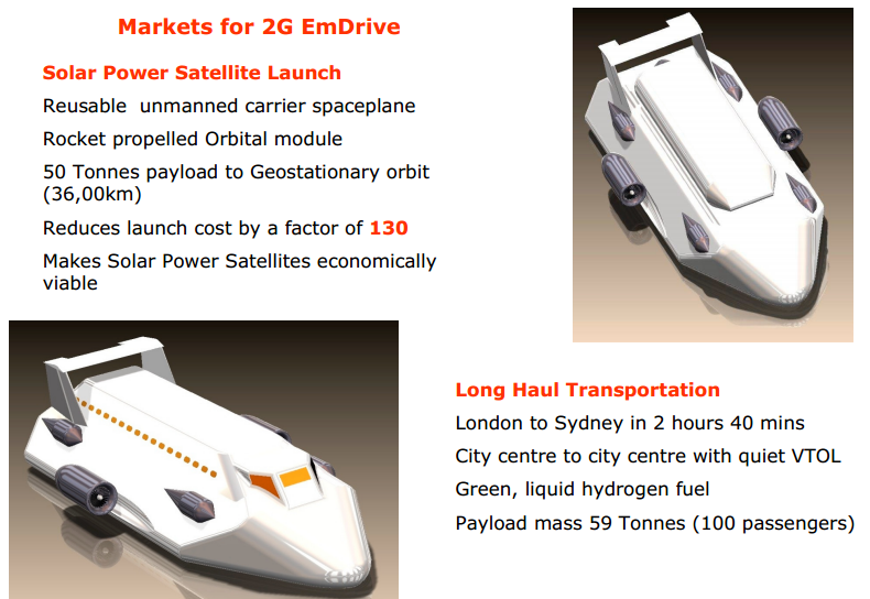
An important application will be a hybrid spaceplane, giving low cost access to geostationary orbit. This will enable Solar Power Satellites to significantly undercut the cost of nuclear power stations, and will give a sustainable solution to the world energy crisis.
The launch sequence is a very slow ascent to above orbital altitude using EmDrive lift engines, followed by separation of the orbital module which then imparts orbital velocity to the payload using conventional rocket propulsion

In 2009, Shawyer was talking about flying cars and test trials in about 2012
The Emdrive Programme – Implications for the Future of the Aerospace Industry
Two other groups, one in China and one in the USA are working on EmDrive projects. We understand that significant progress has been made in both theoretical and experimental work, within these groups. Reports have also been received of work in a further two countries. In the UK we have started the initial performance tests of our first flight thruster. It is anticipated that this thruster will be flown on a technology demonstrator mission.
The main object of this paper is to describe the results of a recent design study for a Hybrid Spaceplane. This vehicle utilises hydrogen cooled, superconducting EmDrive thrusters to provide the static lift. Acceleration is provided by hydrogen fuelled conventional jet and rocket engines. The results of a number of numerical analyses show remarkable performances for different missions. These include sub-orbital passenger transport, Earth orbit payload delivery, and a Lunar landing mission. This design study followed on from the first phase of an experimental, superconducting thruster programme.
It is estimated that the unmanned flying car proposal, using four, liquid hydrogen cooled, versions of the experimental thruster, could begin flight trials in 3 years time.
Superconducting Cavity Thruster and a Proposed Flying Car Demo

The experimental superconducting emdrive

The design of the vehicle results from iterating a mass, power and thrust analysis with inputs from four mission analyses. The mass, dimensions and performance of the jet engines are scaled from the data available for the AMT Titan UAV engine. The power generator is based on an uprated ROTAX 503 aero engine driving a high speed 36 kW alternator.
For 6kW of microwave input power at each thruster, the total lift thrust is 573kg. Thus for an estimated total vehicle mass of 477kg, the vehicle would start to accelerate upwards. However as the average velocity goes above 1m/s, the lift thrust approaches the vehicle mass, and acceleration stops. This is simply the principle of the conservation of energy at work, with energy used to accelerate the vehicle being lost from the stored energy in the thruster, hence lowering the Q.
Clearly, to achieve a useful rate of climb, the jet engines need to be rotated to give vertical thrust and the lift engine operation needs compensation to avoid losing stored energy.
The flight envelope was investigated by running 4 numerical mission analyses. These gave a maximum rate of vertical ascent of 52m/s (170ft/s) and a maximum speed of 118m/s (230 knots) at a maximum altitude of 12.6km (41,300ft). If the altitude is restricted to 1.34km (4,400 ft) then a full liquid hydrogen fuel load will give a maximum range of 97km (60 miles).

Hybrid EmDrive Spaceplane Proposal
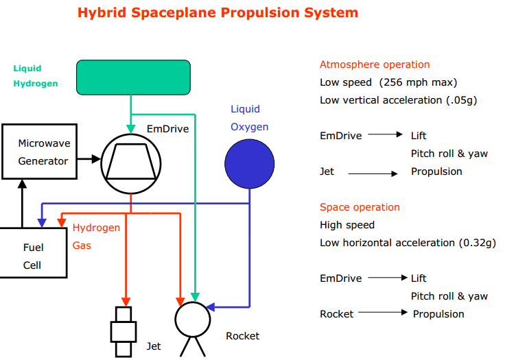
The basic Hybrid Spaceplane (HSP) concept is a VTOL carrier vehicle using eight EmDrive lift engines, two hydrogen fuelled jet engines with vertical lift deflectors and up to six hydrogen/ oxygen fuelled rocket engines. Electrical power would be provided by two fuel cells run on the boiled-off hydrogen gas from the lift engines, and liquid oxygen.
The overall dimensions are 35.5 meters long, 13.3m wide and 7m high. Carrier dry mass is 61.1 Tonnes. Maximum fuel load, liquid hydrogen (LH2) and liquid oxygen (LOX) is 190.5 Tonnes.

The mission analyses show the highest g level to be 0.58 g and maximum velocity in air to be 180 km/hr. However the design is aerodynamic (drag coefficient is estimated at 0.35) and the vehicle is capable of a glide landing in an emergency. Control surfaces for this situation are provided by the twin fin and tailplane configuration
. A 2 meter scale model is shown on the right above.

The London to Sydney sub-orbital mission starts with a vertical take-off with the spaceplane in a horizontal attitude. Lift is provided by the EmDrive thrusters and vertical acceleration by the jet engines. At 12km altitude the ascent rocket engines are fired to maintain the climb to a cruise altitude of 96km At this height, the orbit engines are fired to accelerate the spaceplane to a cruise velocity of 4km/s. At 90 minutes into the flight, deceleration starts, using the lift engines in a braking mode. Note that when used for deceleration, the EmDrive lift engines are not subject to the dynamic thrust limitation, as no energy is being lost from the stored energy in the resonant cavity. Descent and a vertical landing are controlled by both the lift engines and the jet engines.
For the LEO (Low Earth Orbit) and GEO (Geosync Earth Orbit) missions the spaceplane carrier vehicle can be viewed as a “space elevator without cables”.
If you liked this article, please give it a quick review on ycombinator or StumbleUpon. Thanks

Brian Wang is a Futurist Thought Leader and a popular Science blogger with 1 million readers per month. His blog Nextbigfuture.com is ranked #1 Science News Blog. It covers many disruptive technology and trends including Space, Robotics, Artificial Intelligence, Medicine, Anti-aging Biotechnology, and Nanotechnology.
Known for identifying cutting edge technologies, he is currently a Co-Founder of a startup and fundraiser for high potential early-stage companies. He is the Head of Research for Allocations for deep technology investments and an Angel Investor at Space Angels.
A frequent speaker at corporations, he has been a TEDx speaker, a Singularity University speaker and guest at numerous interviews for radio and podcasts. He is open to public speaking and advising engagements.