

The contract for the preliminary design of a Pulse Forming Network (PFN) is part of a larger effort by the U.S. Navy to develop a multimission weapon system for use on naval warships to defend and attack with pinpoint accuracy.
Under the contract, Raytheon will provide the research and development of an advanced Integrated Power Systems power load module that may be used for PFNs to power future lasers, railguns or radars.
The PFN is a large power system providing the electromagnetic energy for the railgun projectile, which will travel up to 220 miles in less than six minutes and exit the atmosphere before hitting its target at a velocity of 5,000 feet per second.
The upcoming phase of railgun development includes demonstrating that it’s possible to fire a railgun at a rate of 10 rounds per minute, as well as doing new kinds of thermal and cooling tests.
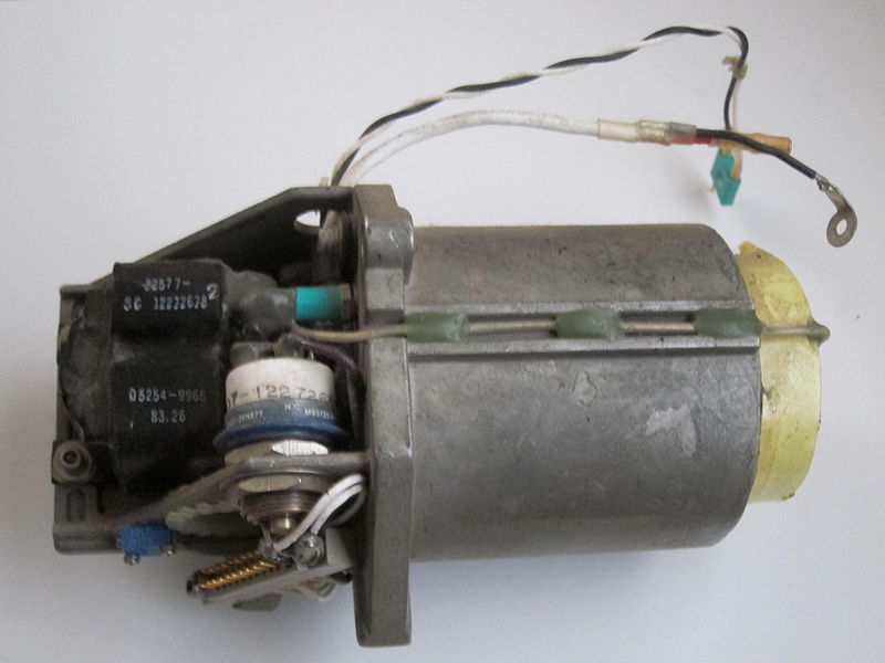
A pulse forming network for an Nd:YAG laser rangefinder.
Wikipedia on pulse forming networks
A Pulse Forming Network (PFN) accumulates electrical energy over a comparatively long time, then releases the stored energy in the form of a relatively square pulse of comparatively short duration for various pulsed power applications. In practice, a PFN is charged by means of a high voltage power source, then rapidly discharged into a load via a high voltage switch, such as a spark gap or hydrogen thyratron. The load may be a high power microwave oscillator such as a klystron or magnetron, a flashtube, or even an electromagnet. Depending upon the application, the output pulse repetition rate may range from a fraction of a Hertz to over 10kHz.
A PFN consists of a series of high voltage energy storage capacitors and inductors. These components are interconnected (as a “ladder network”) that behaves similarly to a length of transmission line. For this reason, a PFN is sometimes called an “artificial, or synthetic, transmission line”. Electrical energy is initially stored within the charged capacitors of the PFN.
Sometimes an actual length of transmission line is used as the pulse forming network. This can give substantially flat topped pulses at the inconvenience of using of a large length of cable.
Upon command, a high voltage switch transfers the energy stored within the PFN into the load. When the switch “fires” (closes), the network of capacitors and inductors within the PFN creates an approximately square output pulse of short duration and high power. This high power pulse becomes a brief source of high power to the load.
Sometimes a specially designed pulse transformer is connected between the PFN and load. This technique improves the impedance match between the PFN and the load so as to improve power transfer efficiency. A pulse transformer is typically required when driving higher impedance devices such as klystrons or magnetrons from a PFN. Because the PFN is charged over a relatively long time and then discharged over a very short time, the output pulse may have a peak power of megawatts or even terawatts.
The combination of high voltage source, PFN, HV switch, and pulse transformer (when required) is sometimes called a “power modulator” or “pulser”.
Space and Nuclear fusion applications from very powerful railguns
HyperV Technologies is trying to develop minirailguns for the world’s first commercially viable fusion reactor technology. Their research could result in the development of a controlled hot fusion reactor that is scalable to provide between 100 MW and 2,000 MW of clean base load electric power.
The methods that HuperV is using does not utilize many of the components in the Navy railgun. HyperV is using imploding spherical plasma liners.
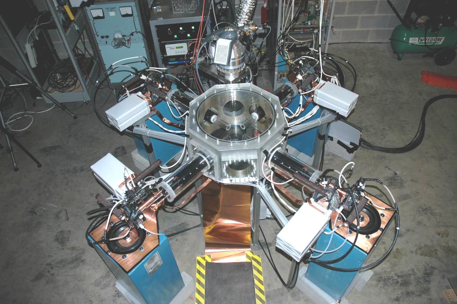
Minirailguns designed to accelerate 8000 micrograms of argon or xenon to 50 km/s are being developed for the PLX project at LANL.
Railgun for space launch

The source of this post is this 10 page IEEE paper, Launch to Space With an Electromagnetic Railgun by Ian R. McNab, Senior Member, IEEE The cost of electricity for a launch will be negligible, as shown below. Barrel life is central to the successful economics for this system. A system might cost $1.3 billion and launch for $500/kg. Recent tests fired 7 pound projectiles at 5637 mph. Lunar escape velocity is 5,324 mph. So the truck sized system is already good enough to launch from the surface of the moon. Classic science fiction “the Moon is Harsh Mistress” by Heinlein could become reality.
Magnetic Catapult for space launch
A 9000 meter long magnetic catapult was proposed in 2003 by Warren D Smith, mathematician at Temple University. It was designed to launch 5 meter long, 1 meter diameter projectiles at 2250 gees of constant acceleration with a launch velocity of 20km/s (twice earth escape velocity, Mach 58). It would cost about $2-20 billion to build and operating costs would be $10-100 million/year. This system is not a railgun and is not a coilgun. It is similar to a superconducting coilgun but is better than the quench gun proposal.

2250 gees would allow electronics to be launched
It is an engineering project on the same scale as the largest particle accelerators. So it is difficult but achievable. The system should be cheaper and safer than chemical rocket launches.
The magnetic catapult would be different from an electromagnetic railgun or linear electric motors.
The magnetic catapult has the following advantages:
1. No electrical or mechanical contact between the projectile and anything else
2. No capacitors or other external energy storage devices. The superconducting magnets of the launcher are the energy storage device and the energy stored is at essentially uniform density in the form of magnetic field.
3. the accumulation of electric power may be accomplished gradually, losslessly and purely mechanically
4. Essentially 100% of the stored energy is converted to projectile kinetic energy. Guns, railguns and rotary pellet launchers suffer damage from friction and other wasted energy.
5. Magnetic catapult has inherently stable operation. Instabilities of other designs at these velocities could be catastrophic.
6. No switching at large current and voltages (like Linear electric motors). Switching only occurs when current and voltage are zero. This minimizes stress on the switch and maximizes energy efficiency.
Railguns use two sliding contacts that permit a large electric current to pass through the projectile. This current interacts with the strong magnetic fields generated by the rails and this accelerates the projectile.

The Magnetic catapult is similar to a superconducting coilguns (quench gun), which are contactless and which use a magnetic field generated by external coils arranged along the barrel to accelerate a magnetic projectile. However, the quench gun releases a lot of heat during coil quenching.

The picture to the left is a standard copper coil coilgun. The magnetic catapult would need cryogenics (to cool the superconductors) and a lot of superconducting material. The magnetic catapult design will need to address the issue of magnetic quenching. During projectile flyby of a superconducting ring, the magnetic environment near that ring can change as much as plus or minus 12 Tesla. to protect against quenching a finely intermixed composite material made of both YCBO and an electrically and magnetically inert companion material is needed. TiO2 might be a suitable material. With a ratio of twice as much TiO2 to YCBO then the inner rings would be 3 times bigger. The total energy losses related to the quenching issue are about 8%.
Another disadvantage is the system does not scale down well, so some test sections could be built but only a nearly full scale system would really indicate if the system would work. However, it seems promising and worth detailed testing and modeling.
The superconducting magnets that are needed for the project are on the leading edge of developments in that area There are record superconducting magnets with 50 cm bore sizes, 7 Tesla and 20 cm bore size, 8.1 Tesla. The full scale system needs 17 Telsa magnets with 100 cm bore size. There is an Atlas hybrid magnet being built to hold 1.2 Gj with 22 meters (2200cm) diameter. The highest power superconducting magnet is 26.8 Tesla and they believe they can soon reach 50 Tesla

Magnet Lab researchers tested a small coil (9.5-millimeter clear bore) in the lab’s unique, 19-tesla, 20-centimeter, wide-bore, 20-megawatt Bitter magnet. However, I think the main issue is one of cost that larger bore sizes mean more wire and more expense. More information on superconducting magnets

A Cern superconducting magnet has an inside diameter of 6.3 meters, a length of 12.5 meters and generates a magnetic field of 4 T (about 80,000 times stronger than the Earth’s). Once completed, the Cms superconducting magnet will boast a notable record: with its 2.6 Gigajoule of energy it will hold the world record of energy ever stored in a magnet.
The magnetic catapult is described in a 42 page postscript file.
The Magnetic Catapult Design
The projectile will be a cylindrical shaped permanent magnet. The accelerator will consist of a sequence of coaxial stationary rings, each of which is also a supercurrent loop magnet. The projectile and the rings all generate the same amount of magnetic flux, which will be assured by initially magnetizing all the rings.
[Thread a ring shaped piece of superconductor with another magnet whose North end is on one side and whose South end is on the other of the ring. cool the ring to ists superconducting temperature, then remove the magnet. Its flux no longer traverses the ring but the total magnetic flux through ring must remain unchanged. More discussion on page 11 of the paper.]
During launch, the projectile passes through the superconducting rings. The South end of the first ring attracts the North end of the projectile. Once the projectile has reached a central position inside that ring (the supercurrent is now zero) and we switch off the superconductivity in that ring converting it into an insulator. The projectile continues on without deaccelerating. This repeats along each of the magnetic rings.
The entire accelerator is enclused in a pipe with a superconducive inner coating. The outer pipe has the following purposes:
1. Is a vacuum vessel
2. It is an EM shield
3. It is a thermal insulator
4. It would help to levitate the projectile
5. The sequence of rings are a long solenoid, the field must come back the otehr way on the outside of the solenoid.
The projectile bursts a membrane at the end of the tube or it passes a double door airlock.
The system should be made in a mountain like Annapurna or Dhaulagiri in Nepal. The projectile would exist above half to two thirds of the atmosphere. The projectile would need to have material that would burn off (ablate) to take away the heat. Only a few percent of the total projectile would need to be sacrificed.
Cost estimate
The Superconducting supercollider (SSC) was to cost $8.25 billion but ran into cost overruns and was cancelled. The SSC was to be in an 87 kilometer long tunnel with 10,000 7m long 6.6 Tesla magnets that were Helium cooled. The Magnetic Launcher would be almost ten times shorter, the magnets need not be as precise, the outer vacuum shells are smaller and the vacuum need not be as high. The Magnetic launcher would be built very robustly and be located on a high mountain. The Brookhaven Relativistic Heavy Ion Collider (RHIC) was 4 kilometers long with 1740 superconducting magnets. The RHIC cost $600 million for $155,000 per linear meter. Those prices would enable the 9 km launcher to be made for $1.4 billion. Another cost estimate looks at costs of components (tunneling, Dewaring, structural support and superconductors) for a maximum cost of $800,000 per meter or $7.2 billion for a 9km long launcher.


Overview of electromagnetic guns
If you liked this article, please give it a quick review on ycombinator or StumbleUpon. Thanks
Brian Wang is a Futurist Thought Leader and a popular Science blogger with 1 million readers per month. His blog Nextbigfuture.com is ranked #1 Science News Blog. It covers many disruptive technology and trends including Space, Robotics, Artificial Intelligence, Medicine, Anti-aging Biotechnology, and Nanotechnology.
Known for identifying cutting edge technologies, he is currently a Co-Founder of a startup and fundraiser for high potential early-stage companies. He is the Head of Research for Allocations for deep technology investments and an Angel Investor at Space Angels.
A frequent speaker at corporations, he has been a TEDx speaker, a Singularity University speaker and guest at numerous interviews for radio and podcasts. He is open to public speaking and advising engagements.